


 Blended Winglets
Rutan-style canard aircraft have conventional winglets at the end of their swept wings. The winglets serve as vertical tails for
directional stability and they increase the wing’s effective aspect ratio. Blended winglets were invented after Burt Rutan exited the
homebuilt aircraft business. Few builders have experimented with blended winglets because it requires structural and aerodynamic
changes to the wing. One person that did was the late Jack Morrison, who added blended winglets to his beautiful E-Racer and then
claimed a 10 knot speed increase. That number seems high, but there’s no doubt that blended winglets have less drag. The Apollo’s
new wing would incorporate them as the baseline design.
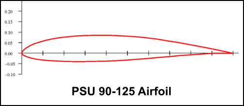
Since the Apollo’s winglets were being optimized, airfoil selection also had to be addressed. Long-EZ derivatives use the E1230 airfoil
with reduced thickness for the winglets. I selected the PSU 90-125 airfoil instead. This airfoil was designed for sailplane winglets at low
RN’s. It has a lower CL max than the E1230 but also has lower drag. Winglet airfoils don’t require high CL max by themselves because
the rudder acts as a flap to achieve the CL’s required for yaw maneuvers.
A common question (and area of disagreement) about blended winglets is: “What is the optimum radius for the blend area?” The answer
depends on several variables, some of which include:
1.
Chord length of the wing tip and winglet root >> this affects the operating RN, boundary layer and flow field.
2.
Relative angle and offset between the wing tip and winglet >> affects interference between the two flow fields.
3.
Speed and wing angle of attack >> determines the inflow that derives the winglet’s angle of attack.
After learning how capable XFLR5 software had become, I began using that tool to investigate different blend radii for the Apollo winglet.
This required some experimentation since XFLR5 does not model blended winglets directly. The creative work-around and full
discussion of analysis results are presented in a report entitled Optimizing Blended Winglet Radii on Homebuilt Canard Aircraft. As a
service to the canard community, that report focuses on the Rutan Long-EZ and its derivative designs. Results for the Apollo aircraft
are presented here:
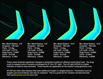
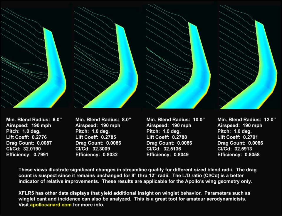
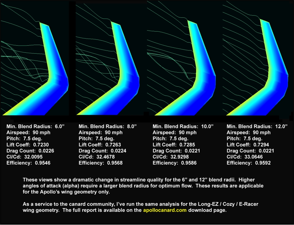
Blend radius values are measured from the top of the wing to the inboard winglet surface at the spar location, which is also max airfoil
thickness. The radius increases towards the leading edge and trailing edge to account for reduced airfoil thickness at those sections.
The pictures above show 2” increments in size, but the analysis included 6” and larger radii in 1” increments. Several observations were
made from the data shown here and other data not presented:
•
The drag data and streamline displays were inconsistent with each other for different sized winglet radii.
•
All blended winglets demonstrated a smooth pressure gradient across the wing-to-winglet transition area.
•
Even the smallest blend radius had better performance than conventional winglets.
•
For the 190 mph flight condition, the 6" radius appears to be on the ragged edge of what is acceptable for this wing. There was
significant improvement with a 7" radius and incremental improvements as the radius increased from 7" to 11", at which point the
streamlines were very smooth.
•
For the 90 mph flight condition, there were strong vortexes for radii up to 9". The vortex was less intense at 10" and straightened
out completely at 11".
It appears that an 11" radius provides optimal performance at low and high speeds. I originally specified a 6” radius to emulate the
blended winglets used on Jack’s E-Racer. The Apollo’s wing tip chord is 28" rather than the 20" chord used on E-Racers, so it makes
sense that the Apollo’s minimum radius would be larger. But there were other considerations and I decided not to use the 11" radius for
the following reasons:
•
The blend transition area is part wing and part winglet, but is not very efficient as either.
•
The larger radius elevates the winglet even further and creates excess vertical tail area, but the winglet cannot be shortened to
compensate (very much) since it contains the rudder and we want to preserve rudder length.
•
To avoid increasing wingspan that would elevate the risk of scraping a winglet at high pitch angles and small roll movements
during the landing flare.
•
To minimize the bending moments created by the winglet during rudder use.
•
To minimize the weight and wetted area associated with the transition area.
•
The smaller radius looks better to most people!
I increased the radius from 6” to 7" because we observed improved streamlines for the 7” radius at the design cruise speed. By not
going to the 11” radius, the climb rate and low speed L/D ratio are not fully optimized. Even so, the performance is already better than
with conventional winglets and there were practical reasons for not going larger.
Other variables that affect winglet performance include the winglet cant angle, incidence, twist, sweepback, and taper ratio. The Apollo
winglet emulates the Rutan designs for these parameters except the cant angle is 3.2 degrees instead of zero. Opening up the angle
between the wing and winglet may reduce interference between the two flow fields and permit a smaller blend radius to be used. The
Berkut winglets have a cant angle similar to the Apollo’s and no detrimental effects have been reported.
Site Map
Email the Designer
Copyright © 2012 Apollo Canard
Blended Winglets
Rutan-style canard aircraft have conventional winglets at the end of their swept wings. The winglets serve as vertical tails for
directional stability and they increase the wing’s effective aspect ratio. Blended winglets were invented after Burt Rutan exited the
homebuilt aircraft business. Few builders have experimented with blended winglets because it requires structural and aerodynamic
changes to the wing. One person that did was the late Jack Morrison, who added blended winglets to his beautiful E-Racer and then
claimed a 10 knot speed increase. That number seems high, but there’s no doubt that blended winglets have less drag. The Apollo’s
new wing would incorporate them as the baseline design.
Since the Apollo’s winglets were being optimized, airfoil selection also had to be addressed. Long-EZ derivatives use the E1230 airfoil
with reduced thickness for the winglets. I selected the PSU 90-125 airfoil instead. This airfoil was designed for sailplane winglets at low
RN’s. It has a lower CL max than the E1230 but also has lower drag. Winglet airfoils don’t require high CL max by themselves because
the rudder acts as a flap to achieve the CL’s required for yaw maneuvers.
A common question (and area of disagreement) about blended winglets is: “What is the optimum radius for the blend area?” The answer
depends on several variables, some of which include:
1.
Chord length of the wing tip and winglet root >> this affects the operating RN, boundary layer and flow field.
2.
Relative angle and offset between the wing tip and winglet >> affects interference between the two flow fields.
3.
Speed and wing angle of attack >> determines the inflow that derives the winglet’s angle of attack.
After learning how capable XFLR5 software had become, I began using that tool to investigate different blend radii for the Apollo winglet.
This required some experimentation since XFLR5 does not model blended winglets directly. The creative work-around and full
discussion of analysis results are presented in a report entitled Optimizing Blended Winglet Radii on Homebuilt Canard Aircraft. As a
service to the canard community, that report focuses on the Rutan Long-EZ and its derivative designs. Results for the Apollo aircraft
are presented here:
Blend radius values are measured from the top of the wing to the inboard winglet surface at the spar location, which is also max airfoil
thickness. The radius increases towards the leading edge and trailing edge to account for reduced airfoil thickness at those sections.
The pictures above show 2” increments in size, but the analysis included 6” and larger radii in 1” increments. Several observations were
made from the data shown here and other data not presented:
•
The drag data and streamline displays were inconsistent with each other for different sized winglet radii.
•
All blended winglets demonstrated a smooth pressure gradient across the wing-to-winglet transition area.
•
Even the smallest blend radius had better performance than conventional winglets.
•
For the 190 mph flight condition, the 6" radius appears to be on the ragged edge of what is acceptable for this wing. There was
significant improvement with a 7" radius and incremental improvements as the radius increased from 7" to 11", at which point the
streamlines were very smooth.
•
For the 90 mph flight condition, there were strong vortexes for radii up to 9". The vortex was less intense at 10" and straightened
out completely at 11".
It appears that an 11" radius provides optimal performance at low and high speeds. I originally specified a 6” radius to emulate the
blended winglets used on Jack’s E-Racer. The Apollo’s wing tip chord is 28" rather than the 20" chord used on E-Racers, so it makes
sense that the Apollo’s minimum radius would be larger. But there were other considerations and I decided not to use the 11" radius for
the following reasons:
•
The blend transition area is part wing and part winglet, but is not very efficient as either.
•
The larger radius elevates the winglet even further and creates excess vertical tail area, but the winglet cannot be shortened to
compensate (very much) since it contains the rudder and we want to preserve rudder length.
•
To avoid increasing wingspan that would elevate the risk of scraping a winglet at high pitch angles and small roll movements
during the landing flare.
•
To minimize the bending moments created by the winglet during rudder use.
•
To minimize the weight and wetted area associated with the transition area.
•
The smaller radius looks better to most people!
I increased the radius from 6” to 7" because we observed improved streamlines for the 7” radius at the design cruise speed. By not
going to the 11” radius, the climb rate and low speed L/D ratio are not fully optimized. Even so, the performance is already better than
with conventional winglets and there were practical reasons for not going larger.
Other variables that affect winglet performance include the winglet cant angle, incidence, twist, sweepback, and taper ratio. The Apollo
winglet emulates the Rutan designs for these parameters except the cant angle is 3.2 degrees instead of zero. Opening up the angle
between the wing and winglet may reduce interference between the two flow fields and permit a smaller blend radius to be used. The
Berkut winglets have a cant angle similar to the Apollo’s and no detrimental effects have been reported.
Site Map
Email the Designer
Copyright © 2012 Apollo Canard